Operation and Precautions of Frozen and Refrigerated Auxiliary Equipment
2025-02-26
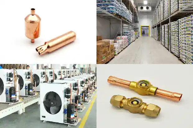
- Liquid Receiver
Function: Store liquid refrigerant for backup and it can also recover refrigerant.
Precautions: The liquid level in the liquid receiver should be between 1/3 and 2/3. The amount of refrigerant charged should not be lower or higher than this standard. - Sight Glass
Function: Display the refrigeration flow rate and water content.
Precautions: - The sight glass on the liquid supply pipeline should be full and bubble - free.
- When the indication color of the sight glass is green, it indicates that the water content in the system meets the requirements. When the indication color is yellow, it means the water content in the system has exceeded the standard. The water content in the system should be reduced by replacing the drier - filter, etc.

- Oil Separator
Function: Separate the refrigeration oil from the high - temperature and high - pressure gas discharged by the compressor to prevent the refrigeration oil from entering the system and affecting the refrigeration effect. - Oil Storage Tank
Function: Store the refrigeration oil separated from the oil separator.
Precautions: - Only use the special oil specified by the unit manufacturer.

- The oil level should be controlled between the upper and lower sight glasses.
- Oil Level Controller
Function: Regulate and control the oil level of the compressor to keep it in the normal position.
Precautions: When the oil level is lower than the lower limit, it indicates lack of oil and the oil circuit should be inspected. - Gas - Liquid Separator
Function: Intercept the possible liquid refrigerant in the low - temperature and low - pressure gas returning from the evaporator to prevent the liquid refrigerant from entering the compressor and causing liquid hammer.
Precautions: Like the return air pipe, it should be wrapped with an insulating layer. - Filters
Classification: Suction gas filter, liquid supply drier - filter, oil circuit filter
Function: Filter impurities in the refrigerant or refrigeration oil.
Precautions: When there are many impurities in the system, the filter should be replaced. - Compressor Head Cooling Fan
Function: Cool the compressor cylinder head by forced blowing to prevent the compressor exhaust temperature from being too high and the refrigeration oil from deteriorating at high temperatures.
Precautions: - Only low - temperature units are equipped with compressor head cooling fans, while medium - temperature units are not.
- It operates synchronously with the compressor itself.
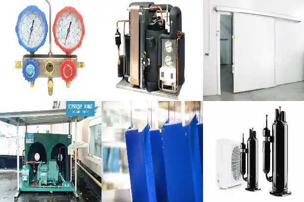
- High - Low Pressure Controller
Function: Control the operation of the compressor within the allowable range. The low - pressure switch also controls the normal start - stop of the compressor.
Precautions: - The high - pressure switch is generally set below 25KG. When the high - pressure switch triggers protection, the heat dissipation of the condenser should be inspected.
- The disconnection value of the low - pressure switch should not be lower than 0kg to avoid damage to the compressor.
- Oil Pressure Controller
Function: Protect the compressor from running in an oil - deficient state to avoid malfunctions.
Precautions: When the oil pressure protection acts, the oil circuit and oil level should be inspected. - Pressure Sensor
Function: Sense the pressure signal and be able to convert the pressure signal into an available output electrical signal according to certain rules. - Vibration - Isolating Pipe
Function: Flexible metal hoses (vibration - isolating pipes) are required to be installed on the suction and discharge pipes of the compressor spring tube to prevent the vibration and noise transmitted by the compressor through the refrigerant pipeline, absorb the vibration generated by the compressor, and protect the entire pipeline system.
Precautions: The vibration - isolating pipe should be as parallel to the crankshaft as possible. During the startup phase, the starting torque of the motor makes the compressor swing from side to side, and the vibration - isolating pipe installed parallel to the crankshaft can easily adapt to this movement. It is not allowed to install the horizontally - installed vibration - isolating pipe perpendicular to the crankshaft.
Related Articles
- Oil Cooling Methods and Oil - changing Operation Procedures for Screw Compressors
- Refrigeration System: Copper Pipe Welding and Flushing Operations
- Essential for Maintenance! Parameters and Phenomena of Normal Operation of Refrigeration and Heating Systems
- What is the Correct Operation Method of the Distribution Box during Cold Storage Installation?
- Operation of Screw - type Water - cooled Chiller Units
- Considerations in Selecting Packaged Air Conditioners and Their Heat Recovery Operations
- Common Malfunctions in the Operation of Cold Storage
- What Are the Three Essential Conditions for the Safe Operation of the Refrigeration System?
- Common Issues in Chiller Operation and Solutions
- Operations and Precautions for Multi - split Air Conditioners: Blowing Debris, Air Tightness, Vacuum Drying, and Refrigerant Charging
- What Should Be Done When the Condenser Fan Doesn't Rotate During Operation?
- Experience Sharing on Refrigeration Welding Operations
- Maintenance and Operation of Freezing and Cold Storage Warehouses
- Cooling Operation of Ammonia Refrigerated Cold Storage
- Water-cooled Screw Chiller: Operation and Maintenance
- Oxyacetylene Welding Operation Method for Refrigeration Pipes
- Defrosting Operation Modes of Refrigeration Equipment and Its Control Components
- Startup and Shutdown Operations of Screw Chiller
